Introduction
Bridging the gap between legacy devices and cutting-edge technology is a fascinating endeavour. If you’ve ever wanted to integrate your 433 MHz remote-controlled devices into your smart home ecosystem using the Sonoff RF BridgeR2, you’re in the right place. In this article, I’ll guide you through the process of flashing the Sonoff RF BridgeR2 with ESPhome, to make it vendor-independent and easily integrable into Home Assistant.
A Caution Against Cheap 433 MHz Modules: While it might be tempting to experiment with low-cost 433MHz sender and receiver modules, my personal experience left me less than impressed. When I attempted to use these modules on a breadboard, I encountered significant noise and interference issues, making it nearly impossible to capture a single RF command reliably. It’s worth noting that sometimes the savings in cost don’t justify the frustration and limitations you may encounter. Surprisingly, the Sonoff RF BridgeR2, priced at around $20, proved to be a cost-effective and highly functional alternative. (You can buy it here if you want to support my website!) Its reliability and ease of use make it a worthwhile investment for anyone looking to integrate 433MHz devices into their smart home setup.
Understanding the Sonoff RF BridgeR2
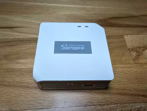
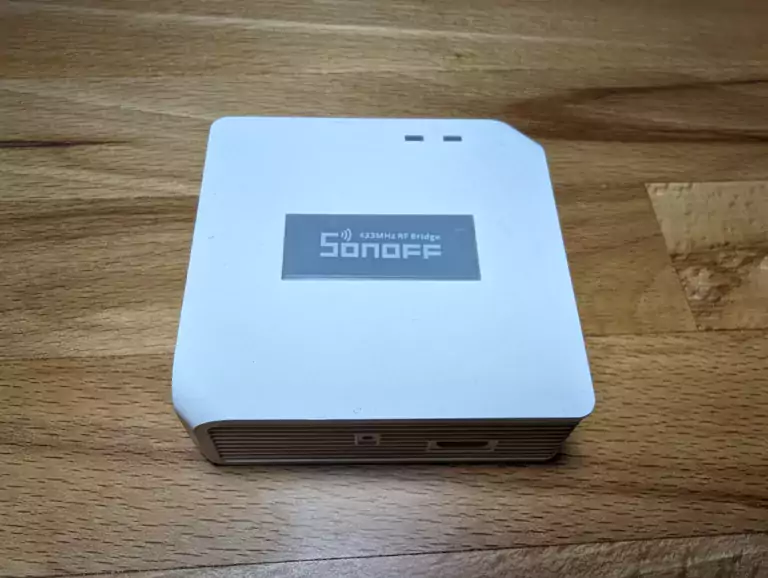
The Sonoff RF BridgeR2 is a versatile smart home device designed to bridge the gap between traditional RF (radio frequency) remote-controlled devices and your smart home automation system.
What is the Sonoff RF BridgeR2?
The Sonoff RF BridgeR2 is the second revision of an 433MHz-to-Wifi bridge from ITEAD, a company that specializes in IoT (Internet of Things) and smart home solutions. This device is part of the Sonoff family, which includes a range of smart switches, outlets, and sensors.
What Does the Sonoff RF Bridge Do?
The primary purpose of the Sonoff RF Bridge is to capture and decode RF signals in the LPD433 UHF band from various remote controls and sensors, allowing you to integrate non-smart, RF-controlled devices into your smart home ecosystem. Here’s what it can do:
- RF Signal Capture: The RF Bridge is equipped with an RF receiver that can capture signals from RF remotes, such as those used for ceiling fans, garage doors, or light switches. It supports a wide range of RF frequencies, making it compatible with many devices.
- Decoding and Translation: Once it captures an RF signal, the RF Bridge can decode and translate it into a format that can be understood by your smart home automation system. This allows you to control RF devices using your smartphone or other smart home controllers.
- Integration with Home Automation Platforms: The Sonoff RF BridgeR2 is compatible with popular home automation platforms like Home Assistant and openHAB. This means you can easily incorporate RF-controlled devices into your existing smart home setup.
- Remote Control: With the help of compatible software or apps, you can remotely control RF devices that were previously only controllable using their dedicated remotes. This adds convenience and flexibility to your home automation.
- Automation and Scheduling: You can create automation rules and schedules for RF-controlled devices, enabling scenarios like turning on your ceiling fan at a specific time or in response to environmental conditions.
In summary, the Sonoff RF BridgeR2 serves as a bridge between RF-controlled devices and your smart home setup, allowing you to modernize and integrate traditional RF-controlled appliances and fixtures into your automated environment. This device is particularly useful for individuals who want to extend the capabilities of their smart home to include non-Wi-Fi or non-Zigbee RF devices.
Preparing the Hardware
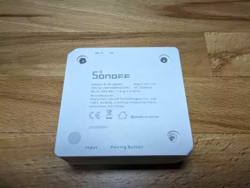
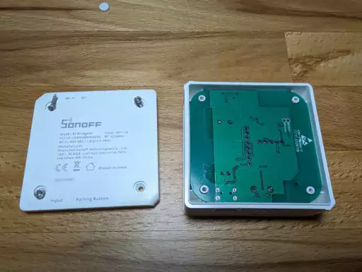
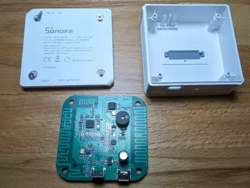
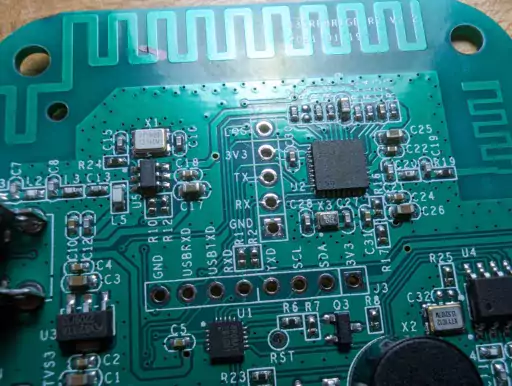
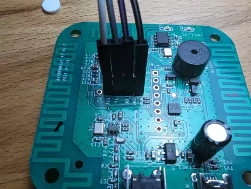
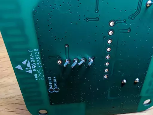
To flash the device and unlock all of its capabilities, it is first necessary to gain access to its serial console. For this, it needs to be dismantled. On the underside are four rubber feet, under which four screws are hidden. Don’t be like me and lose one of the screws and the majority of the feet immediately. Once removed, the underside can be detached and the board is revealed. After the removal of the board, the UART pins can be found.
Preparing the configuration
Before we flash the RF bridge, we can prepare the appropriate configuration file, which will be installed on the device. If you use Home Assistant’s ESPHome Add-On, this will be partially done in advance for you.
First, we set up the name and the board, as well as disable logging to the UART output:
esphome:
  name: rf-bridge
  friendly_name: rf-bridge

esp8266:
  board: esp01_1m

# Enable logging
logger:
  baud_rate: 0
Next up is (mostly) housekeeping – enabling sensors and services, so we can control, update and reset the ESPHome device from Home Assistant.
# Enable Home Assistant API
api:
  encryption:
    key: !secret encryption_key

ota:
  password: !secret password

wifi:
  ssid: !secret wifi_ssid
  password: !secret wifi_password

  # Enable fallback hotspot (captive portal) in case wifi connection fails
  ap:
    ssid: "Rf-Bridge Fallback Hotspot"
    password: !secret fallback_hotspot

button:
  # Restart the ESP
  - platform: restart
    name: "Restart"

uart:
  tx_pin: 1
  rx_pin: 3
  baud_rate: 19200

captive_portal:


# Sensors for ESP version and WIFI information
text_sensor:
  # ESPHome version
  - platform: version
    hide_timestamp: true
    name: "ESPHome Version"
  # IP address and connected SSID
  - platform: wifi_info
    ip_address:
      name: "IP Address"
      icon: mdi:wifi
    ssid:
      name: "Connected SSID"
      icon: mdi:wifi-strength-2
sensor:
  # WiFi signal
  - platform: wifi_signal
    name: "WiFi Signal"
    update_interval: 120s
  - platform: uptime
    name: Sonoff RF Bridge Uptime

binary_sensor:
  - platform: status
    name: Sonoff RF Bridge Status
Next up, we set up a status LED using the bridge’s internal LED. The status LED of the board is on pin GPIO13.
light:
  - platform: status_led
    name: "Switch state"
    pin: GPIO13
Here comes the secret sauce that is necessary to make use of the RF bridging features on home assistant:
api:
  # ...
  services:
    - service: send_rf_code
      variables:
        sync: int
        low: int
        high: int
        code: int
      then:
        - rf_bridge.send_code:
            sync: !lambda 'return sync;'
            low: !lambda 'return low;'
            high: !lambda 'return high;'
            code: !lambda 'return code;'
    - service: learn
      then:
        - rf_bridge.learn
rf_bridge:
  on_code_received:
    then:
      - homeassistant.event:
          event: esphome.rf_code_received
          data:
            sync: !lambda 'return format_hex(data.sync);'
            low: !lambda 'return format_hex(data.low);'
            high: !lambda 'return format_hex(data.high);'
            code: !lambda 'return format_hex(data.code);'
The services need to be added to the api: configuration earlier in the config file.
With this configuration option, you can write complex automations whenever a code is received. To use the code, use a lambda template, the code and the corresponding protocol timings are available inside that lambda under the variables named code, sync, high and low.
Tell the RF Bridge to learn new protocol timings using this action in automations. A new code with timings will be returned to on_code_received Trigger
on_...:
  then:
    - rf_bridge.learn
Configuration options:
- id (Optional, ID): Manually specify the ID of the RF Bridge if you have multiple components.
Note
This action can also be written in lambdas:id(rf_bridge).learn();
At least is the rf_bridge component, with which we register an event handler. With this, the device will automatically forward any RF Codes it receives as an event in home assistant. More about that later.
Flashing ESPHome Firmware
Materials and Tools Needed:
- Sonoff RF BridgeR2
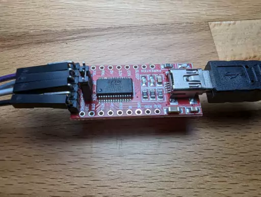
- USB to Serial (UART) adapter (3.3V)
- DuPont wires (female-to-male)
- A computer with a USB port
- Screwdriver
Procedure:
- Prepare the RF Bridge:
- Disconnect the RF Bridge from any power source.
- Identify the Pins:
- On the RF Bridge board, locate the following pins:
- GND (Ground)
- 3V3 (3.3V power)
- RX (Receive)
- TX (Transmit)
- On the RF Bridge board, locate the following pins:
- Prepare the USB to Serial Adapter:
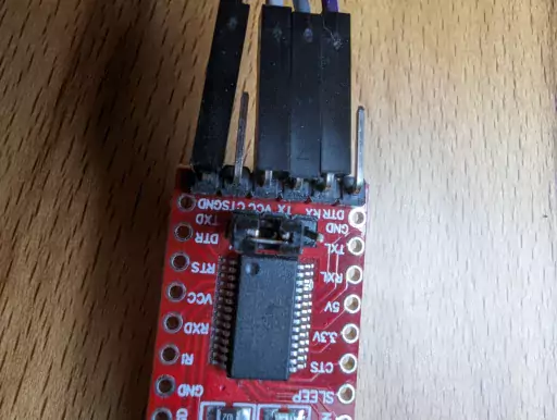
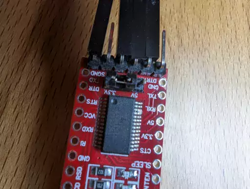
- Make sure the USB to Serial adapter is set to 3.3V (most ESP8266-based devices, including the RF Bridge, require 3.3V logic levels).
- Connect the USB to Serial adapter to your computer via USB.
- Wire the Connections:
- Connect the DuPont wires as follows:
- Connect the GND pin on the RF Bridge to the GND on the USB to Serial adapter.
- Connect the 3V3 pin on the RF Bridge to the 3.3V on the USB to Serial adapter.
- Connect the RX pin on the RF Bridge to the TX on the USB to Serial adapter.
- Connect the TX pin on the RF Bridge to the RX on the USB to Serial adapter.
- Connect the DuPont wires as follows:
- Hold the Bridge in Flash Mode:
- With the wires connected, hold down the reset button on the RF Bridge while connecting it to the USB to Serial adapter. This puts the RF Bridge in flash mode.
- Install ESPHome:
- On your computer, install ESPHome, which is a tool that helps you create and manage firmware for ESP8266-based devices. You can use pip to install it:
pip install esphome. - Alternatively, you can also use Home Assistant’s ESPHome add-on, which takes care of many details.
- On your computer, install ESPHome, which is a tool that helps you create and manage firmware for ESP8266-based devices. You can use pip to install it:
- Create an ESPHome Configuration:
- Create an ESPHome configuration file that specifies the configuration for your RF Bridge and the settings for ESPHome. You can use the ESPHome documentation to guide you through the configuration file creation. Home Assistant does this automatically.
- Flash the Firmware:
- Use the
esphomecommand to compile and flash the firmware to the RF Bridge. The command will look something like:esphome <your_configuration_file>.yaml run.
- Use the
- Monitor the Flashing Process:
- Keep an eye on the flashing process through the terminal. It should display progress information. Wait for it to complete.
- Test and Reassemble:
- Once the firmware is successfully flashed, test the RF Bridge with ESPHome to ensure it’s working as expected.
This process can vary slightly depending on your specific hardware and software setup, so be sure to consult the official documentation for ESPHome for any device-specific details or troubleshooting.
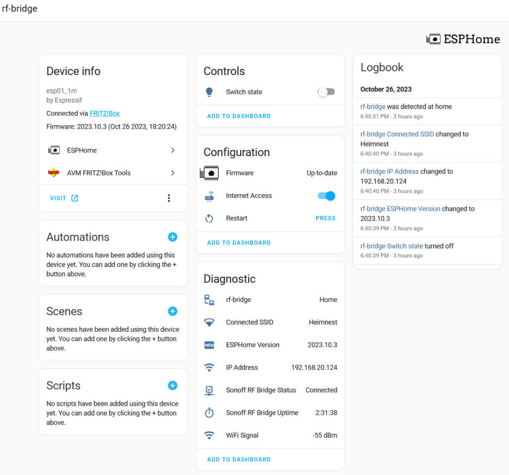
After adding the device to home assistant, it should look like this:
Troubleshooting and Tips
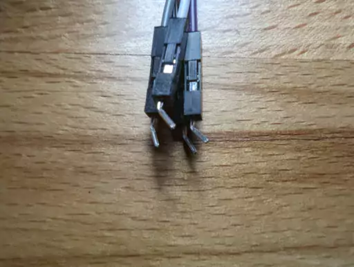
Admittedly, my method of using bent DuPont pins for the flashing process is a bit janky. It worked for me on the first try, but don’t be surprised if it might not work right away for you. Put some pressure on the pins to make sure they keep contact during the flashing process. Furthermore, make sure to hold the reset-pin before plugging in the UART device, so it properly boots into flashing mode.
There’s really not much you can do wrong here, and thanks to the cheap components, there’s also not much to lose.
Conclusion
You can now send and receive RF commands and handle them as events in Home Assistant! Refer to my follow-up article, in which I explain how to not only control “dumb” 433MHz devices via the RF bridge, but also how to make sure Home Assistant stays aware of its state.
If it helped you, and you need one of the components mentioned above, I’d appreciate the purchase via one of the affiliate links – or buy me a coffee if we ever meet!
