Running a Prusa i3 MK3S with Octoprint definitely improves the overall printing experience. You can quickly upload print jobs from the slicer and check on the printing process remotely. Prusa even has a guide on how to install a Raspberry Pi Zero W directly onto the EINSY board. However, the little board struggles to run Octoprint and in some cases it can even cause layer shifts that ruin a print entirely! Doing a Prusa i3 MK3S Raspberry Pi 4 Upgrade is a little more effort, but absolutely worth it.
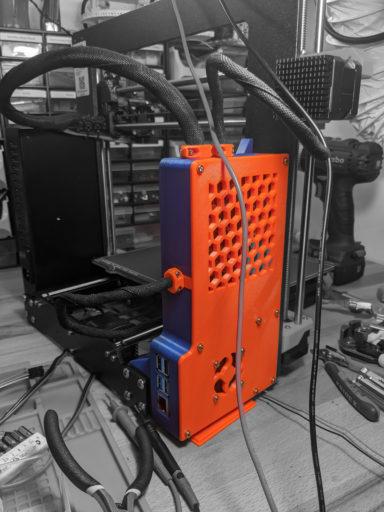
What I enjoyed most about the Raspberry Pi Zero W was how well integrated it was into the case. The printer was still just a single unit that did not have any extra wires hanging around. I wanted to have the same with a more powerful Raspberry Pi board, but it obviously couldn’t fit into the regular case. So I started to look around for a sleek alternative, and found one.
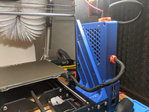
It is the Prusa MK3/S EINSY Raspberry Pi 4B/3B Enclosure with support Brace by KalleKnall. The case not only fits the RPI4 and the EINSY board at the same time, but also increases the sturdiness of the frame by adding a frame brace. Additionally, it also adds ventilation to the case through an optional case fan. My only nitpick would be that some ports of the RPI4 are obstructed, but none of them are really needed as the most important USB ports are easily accessible.
What you need
Here’s a list of tools and materials you’ll need when replicating this build. Some of those are affiliate links; just an attempt to recoup some hosting cost in lieu of using annoying ads.
Material
| Item | # | Comment | Buy |
|---|---|---|---|
| Raspberry Pi | 1 | Anything starting with the 2B ought to work. I used a 4B with 2 GB of memory. | Amazon.com |
| Raspberry Pi Heatsinks | 1 | Since the RPI is already exposed to a rather hot environment, I recommend adding heatsinks to it. | Amazon.com |
| MicroSD-Card | 1 | SD cards have gotten ridiculously cheap. Anything above 8 GB will probably do. | Amazon.com |
| DC-DC Converter 5V/2A (10W) | (1) | In this guide I went with what I had, that is why I used the 10W converter. The manufacturer recommends adding a heatsink when requiring more than 2A. | Amazon.com Banggood |
| DC-DC Converter 5V/5A (25W) (Recommended) | (1) | This is the recommended 25W module, especially if you want to use the RPI to power additional devices! | Amazon.com Banggood |
| Low Noise: 40×40×10 mm fan 5VDC | (1) | This case fan is technically optional but increases the lifespan of both the Raspberry Pi and the EINSY board. The 5V version runs through the DC-DC converter | Amazon.com |
| High Performance: 40×40×10 mm fan 24VDC | (1) | This case fan is technically optional but increases the lifespan of both the Raspberry Pi and the EINSY board. The 24V version runs directly on the Prusa power supply and is relatively noisy. | Amazon.com |
| 2-Pair 1,5 mm² / 16 AWG wire | ~2m | The included wire of the Prusa is too short. Rather than splicing something together, I would recommend getting appropriately gauged wire. Stereo speaker wire seems to make good high-power DC cables. | Amazon.com |
| Jumper Wire | Some jumper wires to connect the internals together. | Amazon.com Banggood | |
M3 Hexagon Full Nut to DIN | 22 | Cable mounts: 8 Raspberry Pi: 4 Einsy Board: 4 Cover: 8 Fan: 4 | Amazon.com |
| M3 Hexagon Nylon Insert Thin Nut | 3 | Brace to Case: 3 | Amazon.com |
| M3 x 8 mm Cap Head Hexagon Socket Drive Screw | 18 | Cable mounts: 8 Raspberry Pi: 4 Case to Frame: 2 Einsy Board: 4 | Amazon.com |
| M3 x 10 mm Cap Head Hexagon Socket Drive Screw | 4 | Brace to Frame | Amazon.com |
| M3 x 12 mm Cap Head Hexagon Socket Drive Screw | 8 | Cover | Amazon.com |
| M3 x 10 mm Countersunk Head Hexagon Socket Drive Screw | 3 | Brace to Case Note: You can make do with regular cap head screws. | Amazon.com |
| M3 x 12 mm Countersunk Head Hexagon Socket Drive Screw | 12 | Cover: 8 Fan: 4 Note: You can make do with regular cap head screws. | Amazon.com |
| M3 Form A Flat Washer | 4 | Brace to frame | Amazon.com |
| M6 3030 T-Nuts | 4 | Brace to frame | Amazon.com |
| M4 x 10 mm Cap Head Hexagon Socket Drive Screw | 2 | Frame | Amazon.com |
| M4 Hexagon Full Nut to DIN | 2 | Frame | Amazon.com |
| Zip Ties | 2 | To tame the cable beast | Amazon.com |
| Spade Wire Connectors | 4 | To crimp the wire ends together. Stranded wire should not be used in screw terminals because it damages the strands. Soldered stranded wire, even less so! Invest in a crimping tool (see below). | Amazon.com |
Tools
| Tool | Comment | Buy |
|---|---|---|
| 3D Printer | Obviously, needed to print the case. | |
| Small Screwdriver | To work on the wire terminals. | |
| Allen Keys | For the M screws. | Amazon.com |
| Multimeter | Checking wiring and voltage levels. Optional but very recommended. | Amazon.com Banggood |
| Soldering Station / Iron | Soldering the pins/cable onto the DC-DC converter. That’s the one I have, which is a bit pricey, but served me well! | Amazon.com |
| Wire Crimping Tool | Crimping the wire ends. Very handy tool. | Amazon.com |
| Lab Bench Power Supply | KORAD KA3005 is the best bang for your buck you can get as a lab power supply. Optional, but useful while doing tests. | Amazon.com |
The Case
Print the Case
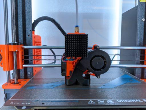
I printed it in PETG, 20% gyroid support and two different colors. The latter primarily because I ran out of orange filament after printing the base, but the two-color scheme actually looks rather good! Even though it does vaguely remind me of hot wheels.
Assemble the frame brace and the EINSY case.
The installation is a little tricky, and the screws going into the frame require strength to cut the appropriate threads into the metal frame. Obviously, make sure you have everything you need printed at this point!
The Electronics & Wiring
Preparing the DC-DC Converter
The Raspberry Pi 4 is rather power hungry, so we cannot use the Einsy board as a power source like the Pi Zero did. Instead, we can hook into the 24 VDC printer power supply and use a DC-DC converter to convert it into the 5V we require for the RP4.
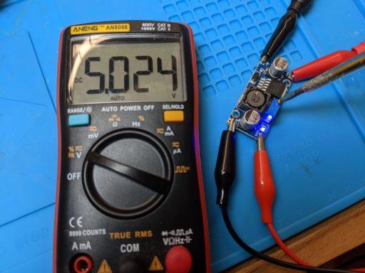
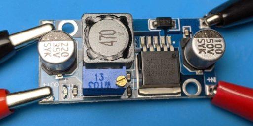
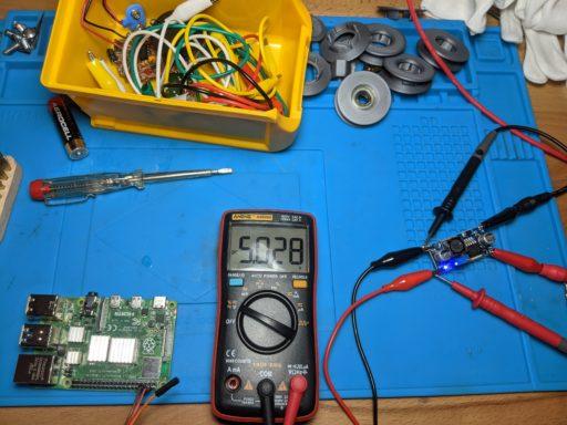
I use a converter that has a variable output. It can take an input voltage of 3-32V and convert it to anything between 5-35V. For our use-case, I hooked the input side to my lab bench PSU set to 24V, and adjusted the little variable resistor until the output voltage was just about 5V. I soldered some pins to the board, so I can use breadboard jumpers for the internal wiring. The wire diameter is a bit thin, but it should be fine.
When using the recommended converter, this step is not necessary. It is already intended for a 5VDC output and has a variable input.
Preparing the Raspberry Pi
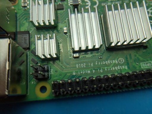
Before installing the RPI into the case, we need to apply the heatsinks to the Raspberry Pi. When installing the heatsinks on the RPI4B, make sure not to short out the capacitor on the board!
Afterward may be a good time to also give the RPI a short test run using the DC-DC converter and a 24VDC power supply (for instance, your lab bench power supply).
Wiring
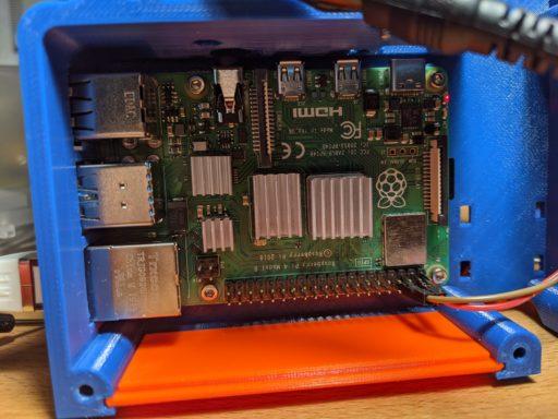
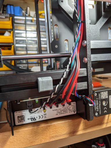
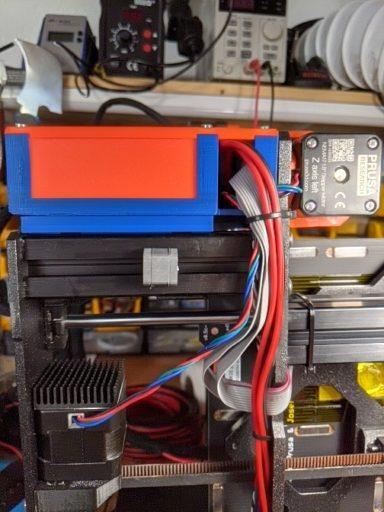
Install all components so you can begin to do the wiring. The installation is a little tedious. Getting the M3 nuts in all the way can be annoying because they tend to shift and get stuck or otherwise refuse to cooperate.
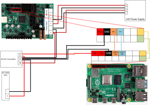
The green connection connects the RPI to the RESET pin on the EINSY board, allowing the RPI to hard-reset the board if necessary. The yellow pin is just another GND pin and can in theory be omitted.
Wire everything as seen above. You can put a ring or spade connector onto the same terminal on the Rambo board as the input wires. As we power the RPI through the DC-DC converter, we don’t need to use the 5V VCC pin of the Rambo board. However, to make the serial communication between the devices possible, they need to share a common ground. That is why the GND pin of the Einsy board also needs to be wired to GND. Complete the rest of the wiring as described in the printer manual.
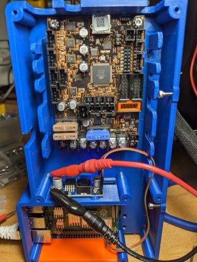
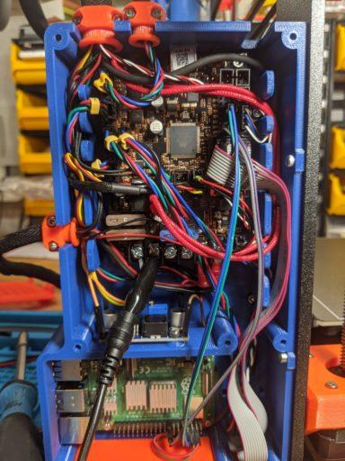
Cut the new power supply wires to the appropriate length and crimp the wire ends with spade connectors. Do not use tinned wire ends! Tinned wires used in screw terminals can become a fire hazard.
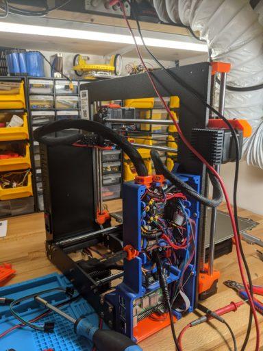
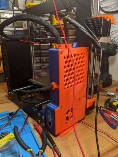
If you chose to also install a fan into the case, this is also the time to put the fan wires on top of the spade connectors before screwing the terminals tight. The wires are solid core, so they do not pose a fire hazard.
Finally — for the serial interface to be enabled on the printer itself, you need to activate the RPi port — this can be done by going to Settings and toggling the RPi port from [off] to [on].
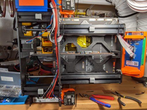
The Raspberry Pi
Install Octoprint and enable the internal serial connection.
Follow the steps as described here to install Octoprint. The prepared SD card can then simply be plugged into the RPI.
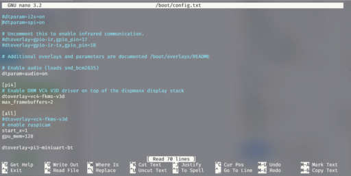
The first thing to do, to enable the internal serial connection of the RPi, is to swap ports used by the GPIO and the internal Bluetooth chip. There is a file called config.txt that can be found in the /boot/ directory. You can open it with nano /boot/config.txt, after which you need to add dtoverlay=pi3-miniuart-bt to the end of the file.
Disable Linux serial console
By default, the primary UART is assigned to the Linux console. Since we want to use this interface for a different purpose, we need to change this. This can be done by using raspi-config:
- Start raspi-config:
sudo raspi-config. - Select option 5 – interfacing options.
- Select option P6 – serial.
- At the prompt
Would you like a login shell to be accessible over serial?answer ‘No’ - At the prompt
Would you like the serial port hardware to be enabled?answer ‘Yes’ - Exit raspi-config and reboot the Pi for changes to take effect.
Adding serial port
Last part of the configuration is in the web interface. Open your browser and type either “octopi.local” or the IP address of the Raspberry Pi. You may need to go through the welcome wizard first.
As soon as you arrive at the home screen, open “Settings” (top right), head to “Serial Connection”, then “Additional serial ports” and insert the following:
/dev/ttyAMA0Save the change and reboot OctoPrint. After the reboot, select the new port and connect to your printer.
Set up your printer profile
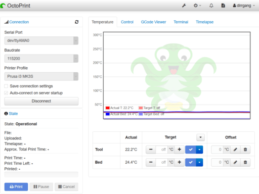
Configure the printer profile as shown below. Notable is the custom bounding box, which prevents “out of bound” errors. These would otherwise occur because PrusaSlicer first places a line of filament outside the printing area to get a proper flow going.
General Settings
- Name: Prusa I3 MK3S (or whatever you like)
- Identifier: (filled in automatically)
- Model: Original Prusa I3 MK3S
Print Bed and Build Volume
- Form factor: Rectangular
- Origin: Lower Left
- Heated Bed: yes
- X: 250
- Y: 210
- Z: 210
- Custom Bounding Box:
- X: 0, 250
- Y: -10, 220
- Z: -1, 210
The PrusaSlicer first prints what is called a purge line outside the actual printing area to get an ideal material flow. That is why the custom bounding box is needed, it prevents Octoprint from throwing errors when the printer wants to print “outside its printing area”.
Axis
- X: 10,200 mm/min
- Y: 10,200 mm/min
- Z: 720 mm/min
- E: 7,200 mm/min
Hotend and Extruder
- Nozzle Diameter: 0.4 mm
- Number of extruders: 1
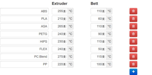
Set up the default filament temperatures (optional)
I’ve added a few of the most common filament types and the default temperatures they’re printed with. This is completely optional.
And we’re done!
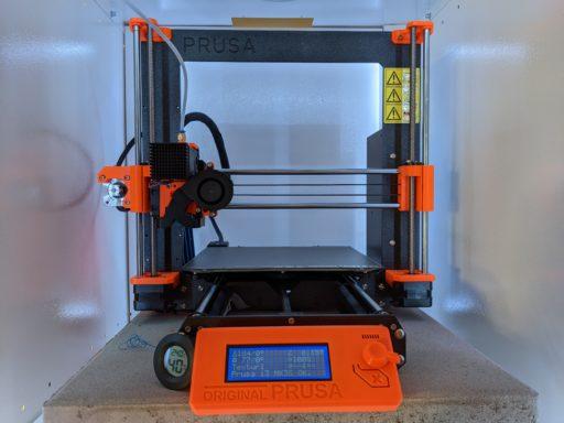
After another XYZ calibration (which you should do whenever you move the printer), it is done. It does look quite nice and sleek, with the RPI integrated in the Einsy enclosure. I’m not sure if it was worth the effort though, in hindsight, a separate case for the RPI with a regular USB cable to the printer might’ve been just as good. Better, even, if placed outside the enclosure, and thus not exposed to the higher temperature.
Something to consider, and possibly do in the future. For now, I’m happy to have replaced the old RPI Zero W with the speedy RPI4.


Is their a step by step guid on how to wire the printer, converter, fan and raspberry. I am left a little confused.
Hello!
I’ve added a more elaborate wiring diagram that should explain how everything needs to be wired. I hope this helps!
Great guide, I just finished my build. Thanks for putting this together!
I did struggle with connectivity between the RPI and Einsy board until I realized that the RPI port on the Einsy board was off by default. Once I turned it on and rebooted, all was well. It might be helpful to include that as a check in your guide.
How do you handle running a 12v fan in the setup? The PSU makes even a super quiet 12v fan scream like a jet engine at 24v. Is there easy access to a 12v supply or did you just run your fan at 24v?
Thank you!
I’ve added a note to enable the RPi port on the printer, as per your suggestion.
Regarding the fan, there might have been a misunderstanding. I am currently running a 24V fan in my build, which is hooked straight into the 24V power from the prusa printer PSU. I will however replace it with a 5V noctua fan to make it quieter.
A 12V fan is a bit of an odd duck in this setup, as there is no real 12V power source available (that I know of. The EINSY board may have 12V afailable somewhere, but I’d advise against that). Definitely do not use a 12V fan on the 24V input – doubling the voltage means quadrupling the power! I doubt any fan will last long under those conditions, and is a likely fire hazard. Inversely, running a 12V fan with 5V is less than one quarter of the power it normally runs under.
So unless you want to run yet another DC-DC converter to get 12V somewhere, I’d advise to just bite the bullet and buy either a 5V or 24V fan.
I have built everything and set everything up, but I am stuck at this part:
The first thing to do, to enable the internal serial connection, is to swap ports used by the GPIO and the internal Bluetooth chip. We need to add dtoverlay=pi3-miniuart-bt to the config file on the boot partition.
Swapping ports used by GPIO and Bluetooth
If anyone can give me a step by step instructions on how to do this I will be complete.
I am stuck here. No sure how to access screen and what sequence of comands to type in.
Any help would be appreciated.
[email protected]
I tried elaborating a little on that part (sorry for the late response!). There is a file called config.txt that can be found in the /boot/ directory of the raspberry pi sd card. You can open it with nano /boot/config.txt, after which you need to add dtoverlay=pi3-miniuart-bt to the end of the file.
Hello,
I’ve followed your instructions but for some reason can’t get it to work…
Am I missing something?
Could you elaborate? What is not working exactly?
Am stuck where Rusty is, how to access the raspi after installing octoprint?
Check out this page as how to access the RPI after installing octoprint: https://github.com/guysoft/OctoPi#how-to-use-it
Awesome job 👍
HI, I plan on installing my pi 4b outside my enclosure since i print at high temp. Could i just use the powersupply that it comes with and only send wire to the pi Tx to einsy Rx and Pi Rx to Einsy Tx?
A bit late, but yes you can. But at this point I’d just use the USB port of the einsy board, because the serial wiring is flimsy and unshielded. I wouldn’t want it to get too long, as it might start to run into issues. USB is shielded and uses twisted pairs to avoid a lot of the potential interference.
Hello Denis,
I am exactly in that same situation than David and I confirm that with a USB connection the system works perfectly.
Before using the USB connection, I’ve tried with the serial wiring, as you propose it, but it did not work at all.
Just note that for having the USB connection working, I’va had to put RPi on “off” in the MK3S panel control.
And a great thank for your explanations.
Francis
I too had everything in place to power my pi via the printer’s PSU but then I finally read up upon the PSU’s specifications: In the end I decided against this route because I saw users reporting failing PSUs even without additional load.
I know they changed the supplier and it seems to be better now with the new, black PSU (old was silver).
The old one is rated for 10A which leaves not much room for powering a 4B when heating the nozzle and bed to high temps. I did not do any calculations on my own, I just chose to believe the guys on the forums.
Mainly, I’m leaving this here for anyone else considering this. Better safe than sorry… ? 🙂
@Dennis you seem to have the black PSU and the blog post is more than a year old — any long term observations?
I’ve had no problems with the black PSU whatsoever. The RPI4 is expected to draw, at most, including an attached camera at full load, about 12.5W of power. The power supply is rated for 240W. It’s true that the PSU of the printer is sized relatively small, but I didn’t have any problems, and Im unaware of anyone who did. Max load on the PSU is during the heat-up phase, which doesn’t last very long.
Your mileage may vary of course, but unless you run your RPI at full load constantly, it should be fine.
Very happy you wrote this post, it helped me quite a bit in the assembly. Wanted to note that I believe the T-Nuts you link to are the wrong size (they are for 2020 extrusions, and the mk3s is 3030). These are a suitable alternative: https://www.amazon.com/gp/product/B09C84TVPK/ref=ppx_yo_dt_b_asin_title_o01_s00?ie=UTF8&psc=1
Sorry about that, I must’ve mixed up something whilte looking for the appropriate ones. I hope it didn’t cause too many problems! I’m glad my post helped you overall though.
Thank you Andrew, I found this out the hard way as well, waiting for the right T-nuts right now. Otherwise a really good design.
Yeah, sorry about the t-nuts. Remember to give a thumbs up to the case designer, KalleKnall. I only wrote a more thorough guide than the original creator did, because I found it to be somewhat lacking.
Many of the hyperlinks on the page are not working. As I would like to try to add this to my printer do you have a list of working URL links for this page?
Only just found this article otherwise would have used your advice already. Great read and much appreciated. Thanks.
Hello!
Sorry, I’ve been using a plugin that’s meant to create static pages for CloudFlare, but it seems like something might’ve broken somewhere. I couldn’t find any broken links, which ones in particular did you mean? (Or did disabling the plugin fix it already?)
Links are working. Thanks.
Thanks for the great guide! Can you comment on the undocumented 2 connections between GPIO pins 15/16 to the Einsy pins 13/14 (the green/yellow wires in the RPi -> Einsy “Power and Data wiring” diagram).
What purpose do they serve?
Thanks for the great guide! Can you comment on the undocumented 2 connections between GPIO pins 15/16 to the Einsy pins 13/14 (the green/yellow wires in the RPi -> Einsy “Power and Data wiring” diagram).
What purpose do they serve?
Pin 13 (green) is the RESET pin, which allows the raspberry pi to “hard-reset” the board. Pin 14 is actually “just” another GND pin, and can in theory be omitted.
Thank you very much for the complete and detailed instructions. I was able to successfully build, wire, and configure the enclosure and the results are great. The look is clean, the RasPi looks like it was meant to be a part of the printer, and the outward facing access to the connections is a nice addition.
Thank you for a wonderful upgrade. I just received the Raspberry Pi 4 and was able to finish the upgrade successfully. There are just 2 things that seem to be different compared to before the upgrade:
1. The Prusa I3 MK3 no longer displays the IP address of the Raspberry Pi.
2. After the printer is left on for a while the Raspberry Pi “seems” to shut down and I have to do a power off and on to get communications active again.
Any suggestions would be appreciated.
Mmh, I’m afraid I don’t know how to help with either problem! I usually turn off my printer whenever I stopped printing, so I never ran into that issue. I suggest checking the RPI logs for clues.
Hi,
Kalleknall here, good work and a very nice Guide 😉
This is a fantastic write up and I plan to follow this guide to do the same thing for my 3D printer. I do have a question, do you know if this enclosure fits a raspberry pi 3B? (I have one and I’m not sure it’s worth upgrading to the pi 4 just so for the purpose of this build). Thoughts?
I think the case fits both 4B and 3B Raspberry Pis!
Thank you very much for the perfect manual!
It works perfectly. And now with a Raspberry Pi 4 it runs more performant and stable.
Wish you all the best in the new year.
Chears Patrick
Great write up, and very helpful. I do have an issue with sending the print straight from PrusaSlicer, but I’ll keep trying to figure this out.
Would have been helpful if you had mentioned you were European beforehand, as I tried inputting your numbers (10 POINT 200 – 10.200) and got nothing but errors. You are saying those are 10200. No need for your punt there, as it is too esoteric. You can write the number without the point or comma, or at least spell out what you mean – ten thousand two hundred is easier to understand than ten point two hundred (as written)
Thanks again, once I figured out what you were meaning to say it went smooth.